Update August, 2025
It's getting real close now. TL;DR here, more information below.
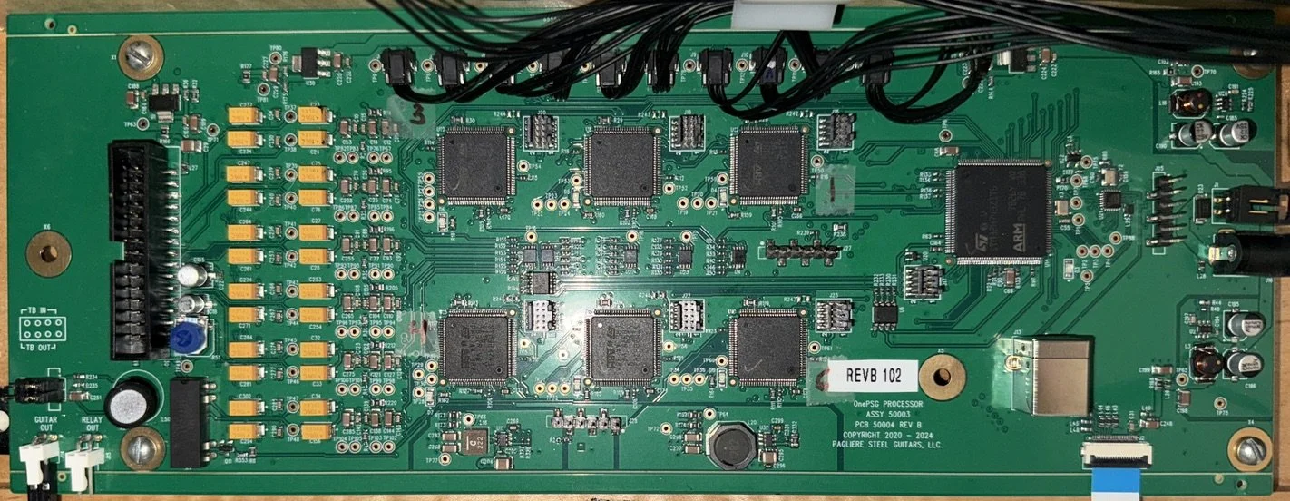
Main PCB for Beta (approx. 10” x 4”)
- Main circuit board designed, assembled, tested. Check.
- Pickup circuit boards designed, assembled. Check.
- Sensor assembly circuit boards designed, assembled. Check.
- Sensor assemblies, final prototype design chosen, 3D printed, assembled. Check.
- Endplates, bridges, tuners/nuts machined. Check.
- Cabinets (one figured maple, one other material) built. Check.
- All cables, connectors (but for endplate connectors) acquired. Check.
- Software ongoing (not blocking assembly)

Pickup PCB for Beta (approx. 4” x 2”)
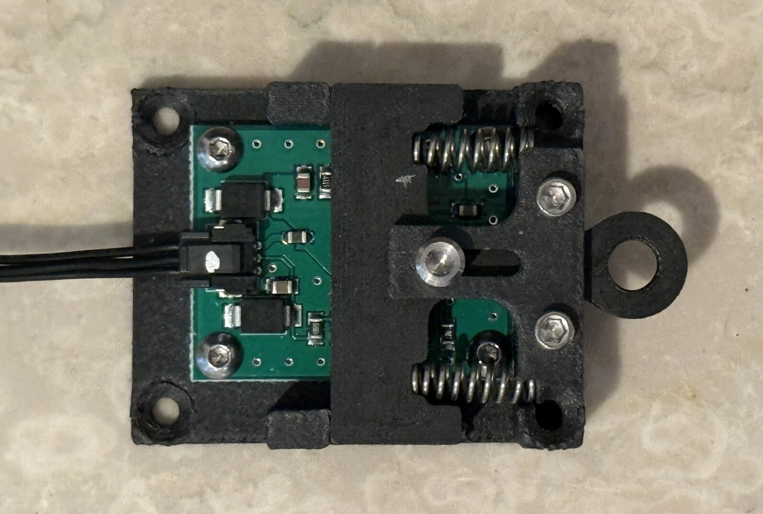
Sensor assembly for Beta, for pedals and knee levers (with PCB) (approx. 1.25” x 2”)
Next steps: After the choices for the endplate connectors are nailed down, there’ll be nothing preventing Alan from jumping on a plane (except the state of the airspace, perhaps ;) ), and heading out to meet up with Ross Shafer for the “Assembly Party” during which they’ll put together everything listed above.
Non-TL;DR
In the Control/Main PCB photo:
the cable header for the pickups’ input (on the left)
the cables coming from the pedals and levers to the connectors (at the top)
the one main microcontroller (MCU) and the six DSP MCUs (for up to 12 strings)
the cable to the touchscreen (lower right)
the audio output terminals (lower left).
In the pickups PCB photo you can see the ten individual single-string pickups (cycfi.com’s amazing Nu pickups).
In the photo of the sensor assembly (currently 3D printed in-house using carbon fiber impregnated filament; eventually likely machined in metal), you can see:
the “backplate” which attaches to the guitar’s apron and to which the sensor PCB is attached.
the “tab” with its hole to allow for a pedal rod or knee lever connection, which holds the magnet and set screws for magnet adjustment.
the “keeper” which holds the tab in place.
return compression springs